
XTND4K14140TPC
HDMI Splitter/Extender, HDMI 2.0, HDBaseT 18 Gbps HDR Extender, 4K to 40M
XTND4K14140TPC
HDA, HDMI Extenders, Splitters & Switchers, AV Matrix Switchers, HDMI Extenders
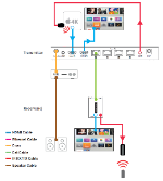 (click to expand) |
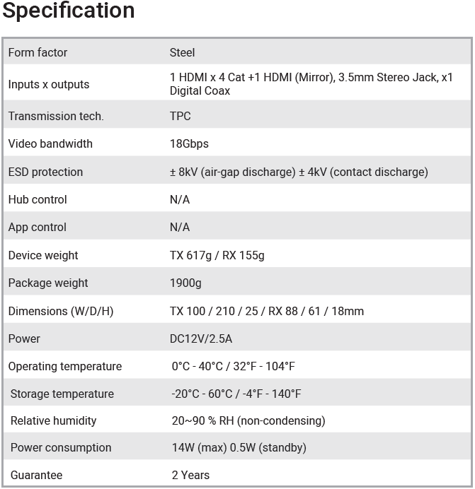
HDMI 2.0/HDBaseT 2.0 18Gpbs HDR Splitter/Extender
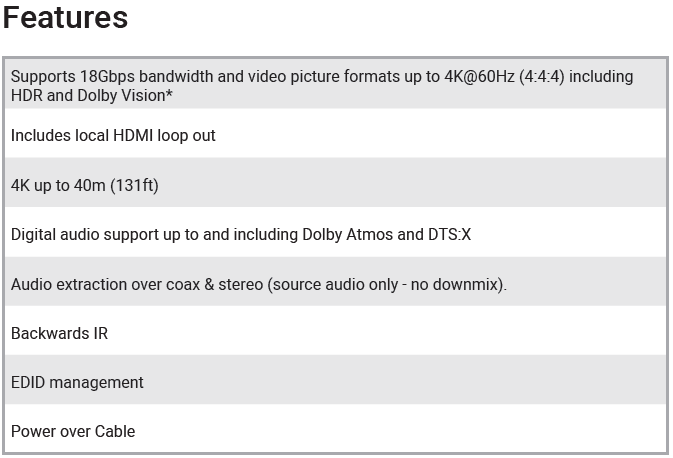
Designed for the most modern home entertainment market requirements, the XTND4K14140TPC is fully HDMI 2.0 compatible, boasting 18G HDMI interfaces that support the latest 4K HDR video content, as well as 1080p, and Dolby Atmos surround sound.
This is distributed over a single Cat6 cable to 4 display locations, up to 40m/60m away with no latency, providing PoE power to the receivers, plus 1 HDMI out for a local display or daisy-chaining with another XTND or HDMI device.
Stereo or multichannel audio extraction is also available for media room setups.
Tipping Point Compression (TPC) enables the transmission of premium UHD/4K 60Hz 4:4:4 content, including (HDR10) over a single Cat6 cable, with no human-perceivable difference in video quality.
(Product Code: XTND4K14140TPC SKU: 2.50.892)

Control
- IR 1-Way (from screen to source)
- Sky TV tested (including new smaller KAON set top box)
- Receiver and flasher dimensions as below
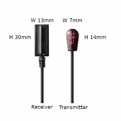
NOTE: Make sure the IR Emitter is positioned correctly in front of the IR window on your source device. IR windows may vary in position depending on source/model.
Advanced Control
- RS232 Not applicable
- Third Party Not applicable
- App Control Not applicable (details below for models that apply)
ControlImprove your multiroom HD smart home experience with the HDanywhere Control app for phone or tablet. Watch TV your way Optimised for all devices |
HDBaseT Wiring Guidance
HDA video distribution systems require a single network cable to be run from each HDTV location, back to a central point. Some single wire systems use HDBaseT technology to transmit over 1 x Cat5e/6/7 cable up to a 100 Metre distance.
This article is designed to give you a good overview of the standard of wiring needed for a HDBaseT system.
What is HDBaseT?
HDBaseT is a transmission technology widely used for whole-home and commercial distribution of uncompressed HD multimedia content. The cornerstone of HDBaseT technology is 5Play™, a feature set made up of five key things that are sent over a single Cat cable:
- Uncompressed high-definition (HD/1080p) and 3D video, plus 4K resolutions
- Lossless digital audio formats 7.1 and beyond
- High-speed Ethernet 100BaseT scaling up to Gigabit
- 100w power over HDBaseT (PoH) up to 100m
- Various backward + forward control signals (IR, USB, RS232)
What is the best type of cable to use?
Currently you can use Cat5e, Cat6, Cat6e, Cat6a, Cat7 or Cat7a with HDanywhere HDBaseT-based products. The baseline cable standard for HDanywhere systems is Cat5e. Slightly greater distances can be achieved by using Cat6, or slightly better still with the Cat7, which have thicker copper cores for easier signal transfer.
DO NOT USE COPPER CLAD ALUMINIUM (CCA) Cat 5/6/7 CABLE FOR HDBASET PRODUCTS.
Whichever network cable type you choose, ensure that the main wiring architecture is ‘solid core’, not stranded ‘patch’ cabling. Patch cabling can be used for the last few metres of a run (say from a wallplate) but should be avoided over the longer runs as signal transfer over stranded cores is heavily reduced.
The use of pre-made leads is not recommended unless you can be absolutely sure of their construction credentials (i.e. solid core 568B)
-
Shielded cables
Unlike other systems, shielded FTP cable is not a stipulation. If however you preferred this type of cable please ensure compatible shielded accessories are used. Failure to terminate cable screen at all points can induce interference rather than eliminating it.
-
Best Practice
Best practice advice is to always use a straight piece of cable terminated directly at the matrix and the receiver ends.
-
HDBaseT with patch panels & wall plates
If the patch panels are terminated correctly and well, there is minimal loss of distance with HDBaseT.
The use of wallplates and patch panels always has the potential to cause increased resistance on the cable, introducing ‘pinch points’ for signal transmission and could reduce advertised transmission lengths.
TIP – instead of using RJ45 wallplates, use brush plates instead to maintain the neat finish. A search for “brush plates” will yield many results.
-
Can I use HDBaseT Extenders over PowerLine?
HDBaseT is not a signal type that can travel over powerline/homeplug network extension systems.
-
Connection termination
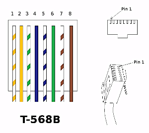
Terminate the cabling using RJ45 connectors to the 568B wiring standard (shown below).
-
General Troubleshooting Advice
Check that the Cat cable is not bent, knotted, kinked or distorted in any way that would prevent these high frequency signals from traveling throughout the intended length.
Also, ensure that the cables as far away from potential sources of EMI (Electro-Magnetic Interference) such as electrical cables, transformers, light fixtures, etc.) as possible. Cables should maintain a 300mm separation from power cables.
Try re-terminating the RJ45 connectors again, making absolutely sure that every termination is perfect. Ensure that the RJ45 connectors are fully inserted and click locked into place firmly and securely to ensure perfect connector connection
-
Suggested Installation Do’s and Don’ts
DO maintain the twists of the pairs as close as possible to the point of termination, or no more than 13mm untwisted.
DO make only gradual bends in the cable where necessary to maintain the minimum bend radius of 4 times the cable diameter or approximately 30mm radius.
DO use low-to-moderate force when pulling cable. The standard calls for a maximum of 34 N-m (newton-metres of force).
DO use cable pulling lubricant for cable runs that may otherwise require great force to install. (You will be amazed at what a difference the cable lubricant will make)
DO keep Category cables as far away from potential sources of EMI (Electro-Magnetic Interference) such as electrical cables, transformers, light fixtures, etc.) as possible. Cables should maintain a 300mm separation from power cables.
DON’T allow the cable to be sharply bent, twisted, or kinked at any time. This can cause permanent damage to the geometry of the cable and cause transmission failures.
DON’T over-tighten cable ties or use plastic ties.
DON’T EVER splice or bridge Category cable at any point.
DON’T use excessive force when pulling cable.
DON’T use oil or any other lubricant not specifically designed for Category network cable pulling as they can infiltrate the cable jacket, causing damage to the insulation.
DON’T tie cables to electrical conduits, or lay cables on electrical fixtures
DON’T install cables taut. A good installation should have the cables loose, but never sagging.
DON’T use staples on Category cable that crimp the cable tightly. The common T-18 and T-25 cable staples are not recommended for Category cable. However, the T-59 insulated staple gun is ideal for fastening both Category and fibre optic cabling, as it does not put any excess pressure on the cable.
DON’T use patch cords (cables) or punch down blocks.
| Sky TV Set Top Box Output Resolution |


